Configuring the output
Servos are typically mapped to simulator variables that output numerical values, and require positive integer inputs between 0 and 255. Most simulator variables will require scaling to work properly with these servo input ranges.
The following steps demonstrate how to use a servo and MobiFlight value modifiers to display the flap position in a Cessna 172 in Microsoft Flight Simulator 2020 and Microsoft Flight Simulator 2024.
Tip
The steps for using a servo in an X-Plane project are similar. Use the X-Plane DataRef type when configuring the Sim Variable tab.
Add a new output config
Click the Add Output Config button in the main MobiFlight window to open the output configuration dialog.

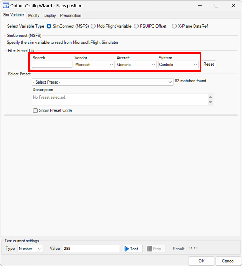
Filter the output presets
On the Sim Variable tab, use the Filter Preset List dropdowns to filter by Microsoft, Generic, and Controls.
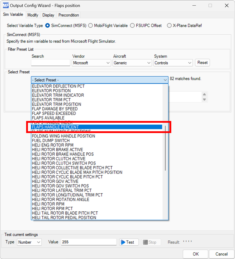
Select the flaps position preset
Use the Select Preset dropdown to select the FLAPS HANDLE PERCENT preset.
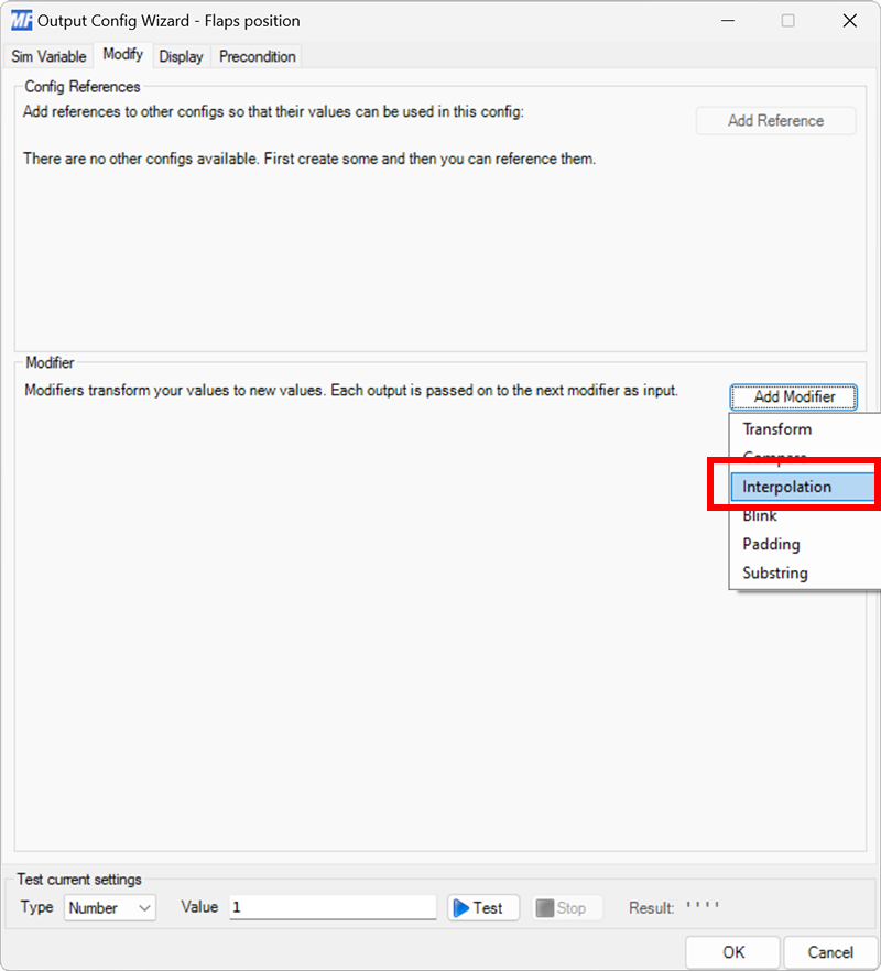
Add an interpolation modifier
On the Modify tab, click the Add Modifier button and select Interpolation to add a new modifier to the output configuration.
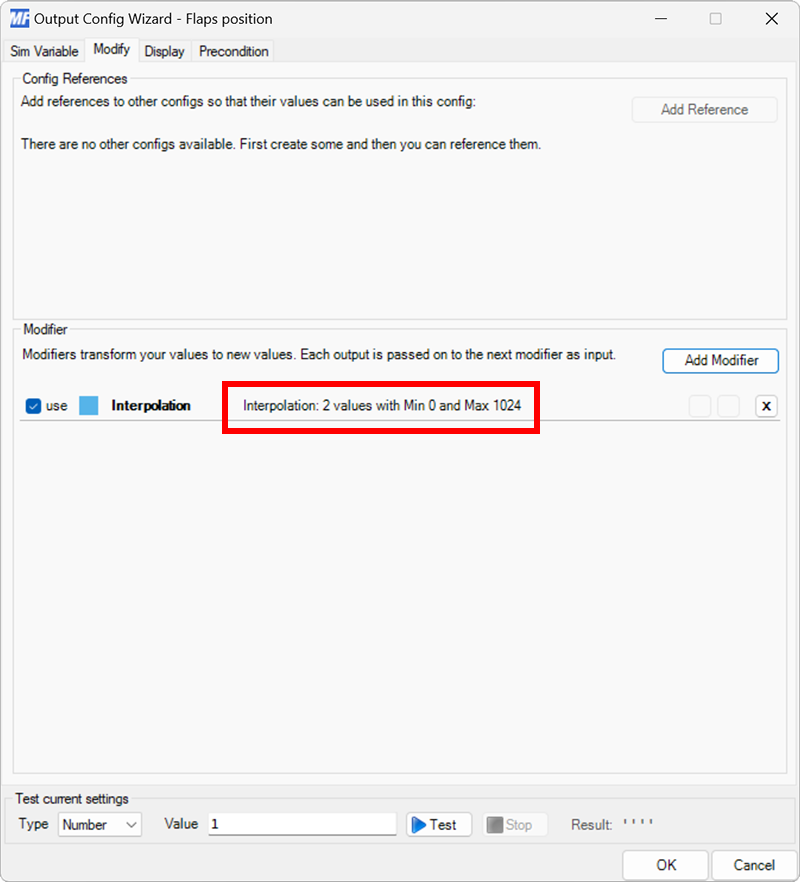
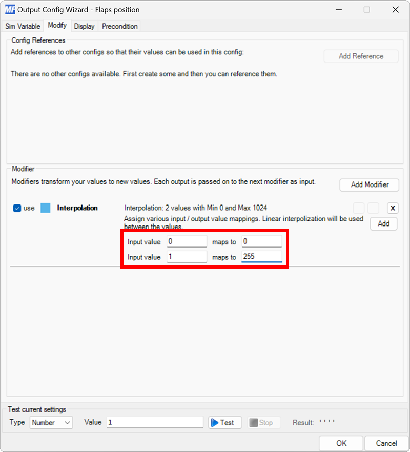
Edit the modifier
Click the Interpolation: 2 values with Min 0 and Max 1024 text to enter edit mode.
Set the interpolation values
Since the value range from the simulator is 0–1 and the servo requires a value of 0–255, set the first Input value row to map 0 to 0 and the second Input Value row to map 1 to 255.
Tip
The values can be inverted by mapping 0 to 255 and 1 to 0, if necessary.
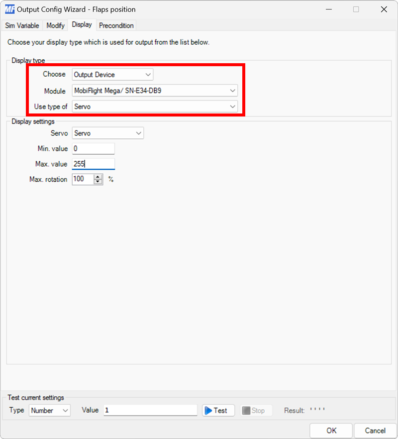
Select the board and device type for the output
On the Display tab, use the Module and Use type of dropdowns to select your connected board and the Servo device type.
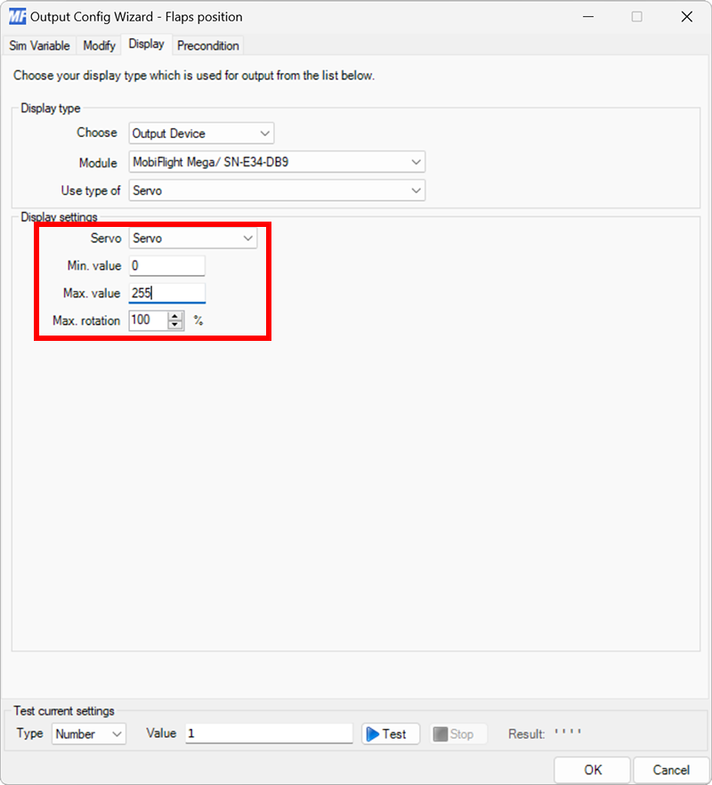
Configure the servo for display
Use the Servo dropdown to select the servo that should display the output value. Since the modifier adjusts the flaps handle position to a value from 0–255, set the Min. value to 0 and the Max. value to 255.
Tip
To reduce the range the servo moves, adjust the Max. rotation value.
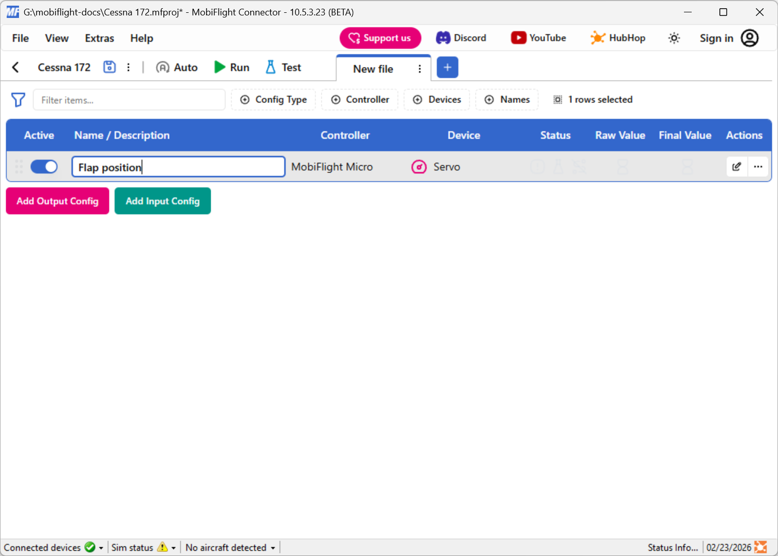
Close the dialog and name the config
Click the OK button to close the dialog, then double-click on the New Output Config name in the main window.
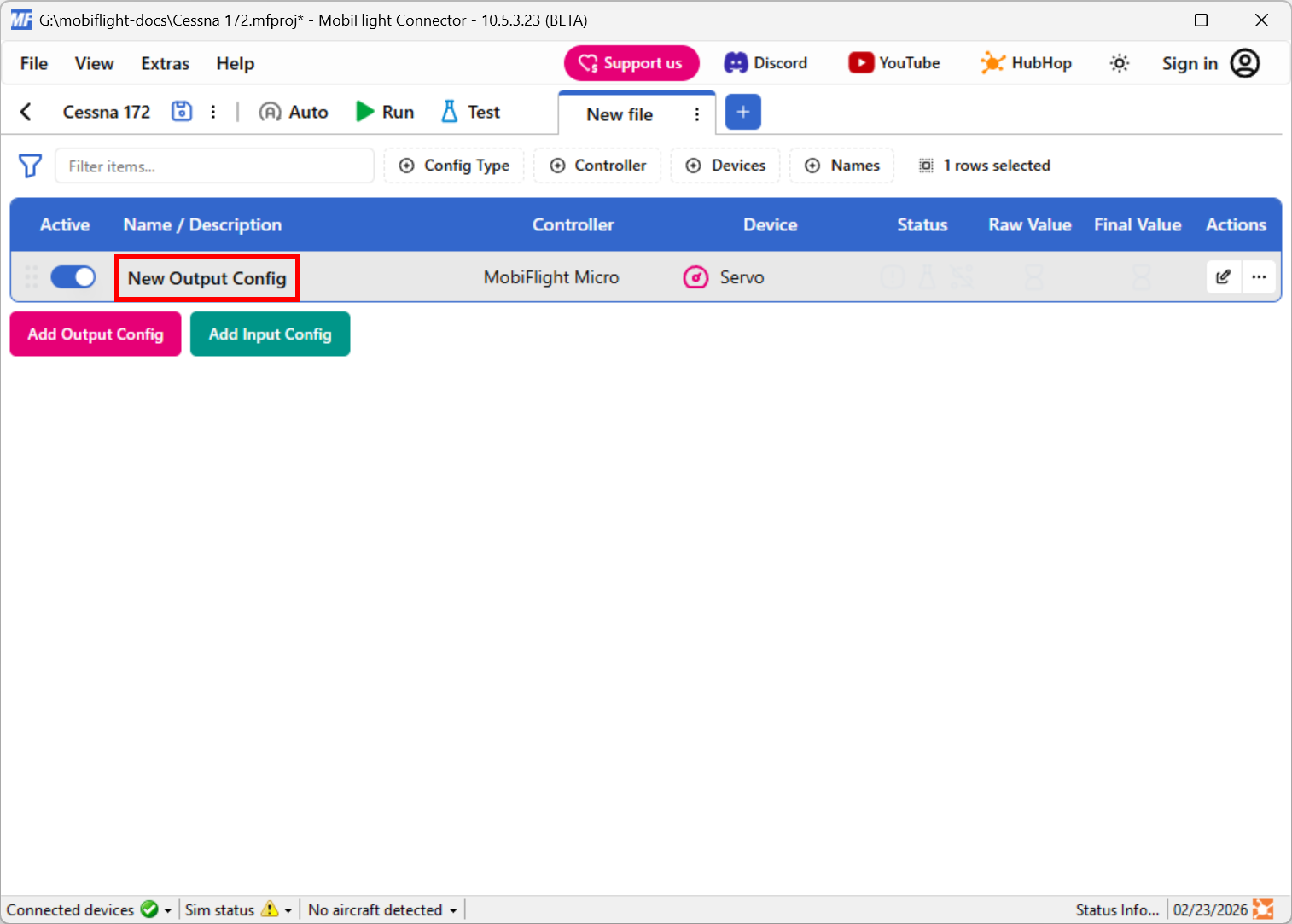
Type in a meaningful name for the new config, for example Flap position, and press enter to apply the change.
Try out the event
Spawn an airplane in Microsoft Flight Simulator. Make sure the MobiFlight Run button is clicked in the toolbar, move the flaps handle in the simulator, and verify the servo changes position.
Tip
Even though these steps are for a Cessna 172, the same flap position configuration should work for most planes in Microsoft Flight Simulator.