Adding the device
Open the settings dialog to edit modules
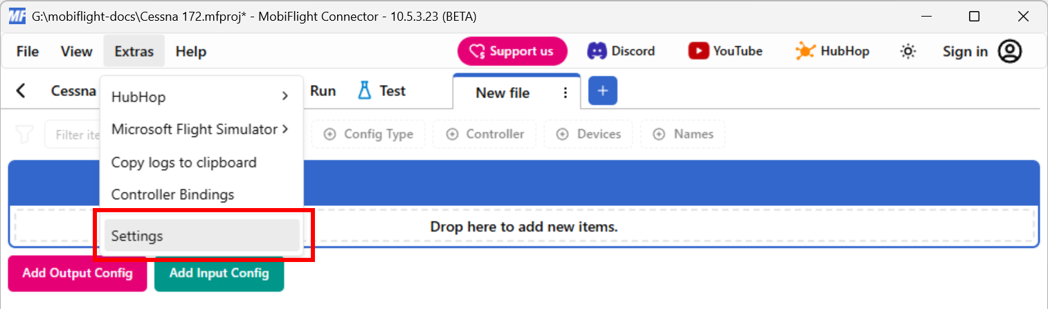
Click on the Extras menu and select Settings to open the settings dialog.
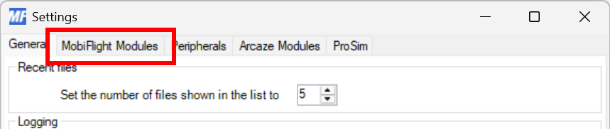
Then click on the MobiFlight Modules tab to display the modules.
Add the multiplexer
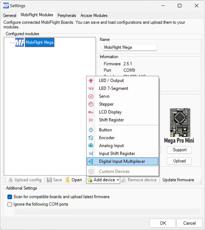
Click on the board the device is connected to, then select Digital Input Multiplexer from the Add device menu.
Configure the multiplexer
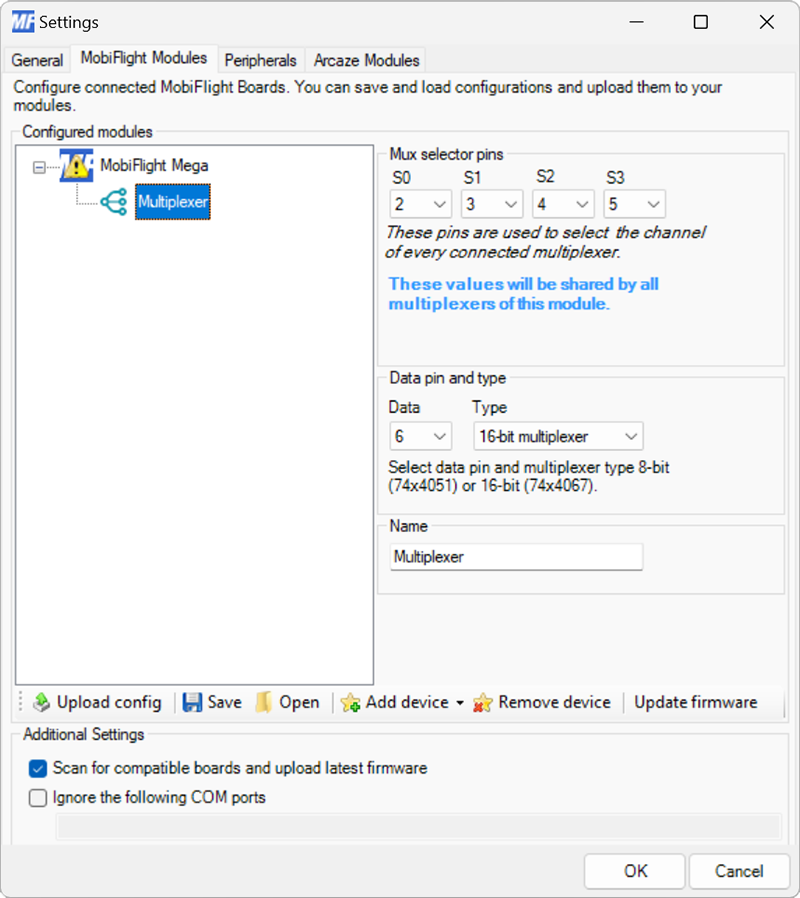
Use the S0, S1, S2 and S3 dropdowns to specify the board pins used. Set the Data dropdown to the board pin connected to the SIG pin on the breakout board.
Specify the size of the multiplexer using the Type dropdown. Use 8-bit multiplexer for 74HC4051 chips and 16-bit multiplexer for 74HC4067 chips.
Provide a meaningful name for the multiplexer in the Name field. This name is shown in the input configuration screens when assigning the multiplexer to a flight simulator input.
Tip
When connecting additional multiplexers to the same board, they can share the S0–S3 pins. Each multiplexer must use a dedicated Data pin.
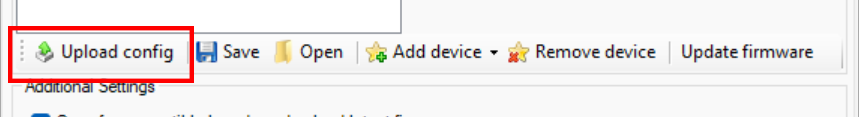
Upload the changes to the board
Click the Upload config button at the bottom of the MobiFlight Modules tab to upload the modified configuration to the board.
Close the MobiFlight modules dialog
Click the OK button to close the MobiFlight modules dialog and return to the main app window.